
Warning: You are viewing an older version of this documentation. Most recent is here: 42.2.0
Stamus Network Appliances
This page is specific to Stamus Network Appliances deployment and installation.
If you are installing our software on Virtual Appliances (virtual machines) or On Premise, continue with Installating Stamus Central Server.
Appliances Models
Model |
Product ID |
Product |
|---|---|---|
SYS-STS100-000 |
SN-PA-100M |
Stamus Network Probe (100Mbps) |
SYS-STS200-000 |
SN-PA-1G |
Stamus Network Probe (1Gbps) |
SYS-STS300-000 |
SN-PA-10G |
Stamus Network Probe (10Gbps) |
SYS-STS400-000 |
SN-PA-40G |
Stamus Network Probe (40Gbps) |
SYS-STS500-000 |
SN-SCSA |
Stamus Central Server |
Note
All models require an USB Keyboard and a VGA monitor (or an adaptator for VGA) to be able control the boot process of our Appliances.
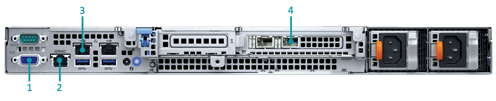
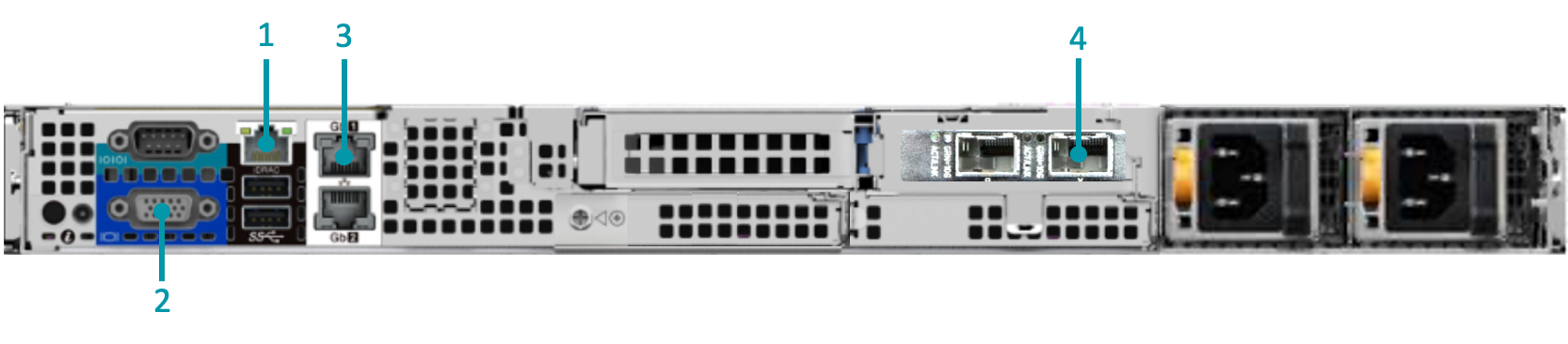
Stamus Central Server
SYS-STS500-000 (SCS)
Box content
1x server unit (1U)
1x documentation - “Enterprise Products Safety, Environmental, and Regulatory Information”
2x power cord C13-C14 2Ft
1x front bezel with Logo “STAMUS NETWORKS SCSA” + key
1x “1U Cable management arm kit” box
1x “KIT, RDYRL, 1U” box
Hardware Setup
Reference |
What it is |
Role |
|---|---|---|
1 |
Standard VGA output |
Attach a VGA compatible monitor |
2 |
iDRAC Ethernet port |
Optional, see iDRAC setup |
3 |
1GbE Ethernet port |
Probe Management Port |
4 |
10GbE SFP+ port |
Probe Management Port |
Note
Depending on your environment, the management port could either be the first copper 1 GbE port or the first SFP+ 10 GbE optical port
Stamus Network Probes Appliances
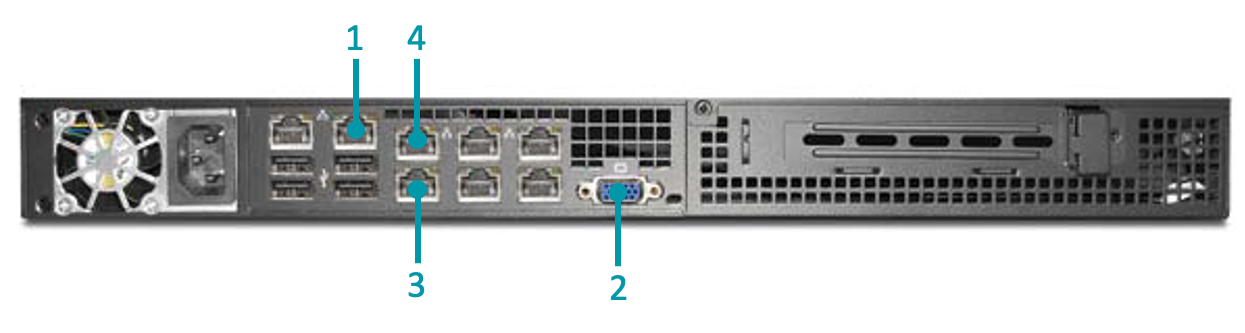
SYS-STS100-000 (100Mbps)
Box content
1x server unit (1U)
1x Installation guide
1x power cord C13-C14 10Ft
Hardware Setup
Reference |
What it is |
Role |
|---|---|---|
1 |
IPMI ethernet port |
Optional, see IPMI setup |
2 |
Standard VGA output |
Attach a VGA compatible monitor |
3 |
100Mb Ethernet port |
Probe Management Port |
4 |
100Mb Ethernet port |
Sniffing port |
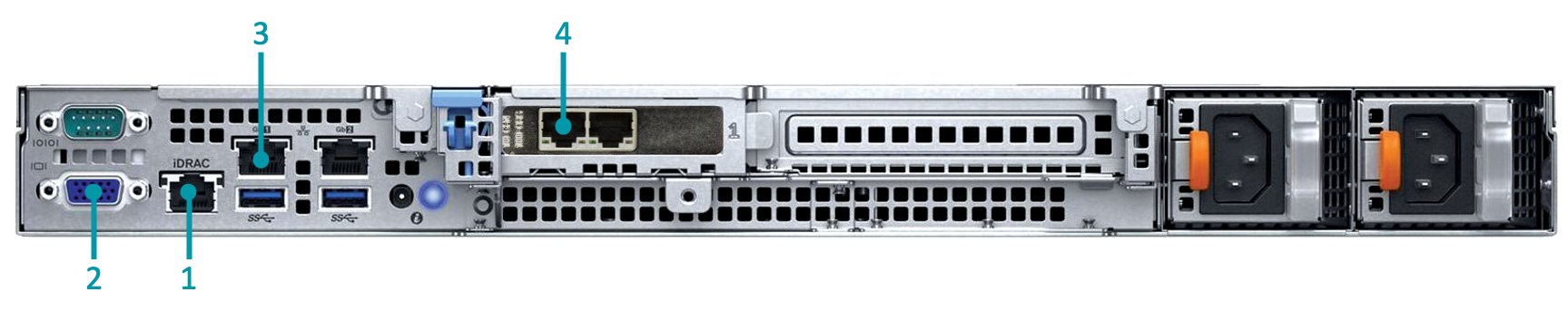
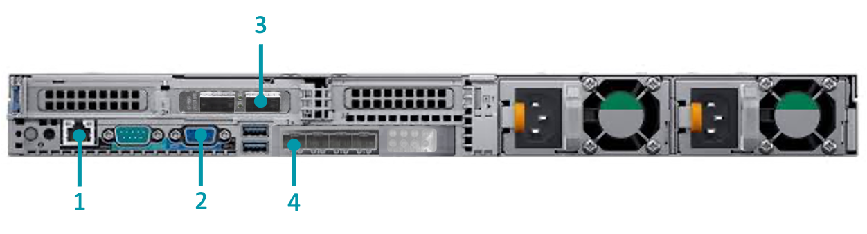
SYS-STS200-000 (1Gbps)
Box content
1x server unit (1U)
1x documentation - “Enterprise Products Safety, Environmental, and Regulatory Information”
2x power cord C13-C14 2Ft
1x front bazel with Logo “STAMUS NETWORKS 1G” + key
1x “1U Cable management arm kit” box
1x “KIT,RAILS,SLIDING” box
Hardware Setup
Reference |
What it is |
Role |
|---|---|---|
1 |
iDRAC ethernet port |
Optional, see iDRAC setup |
2 |
Standard VGA output |
Attach a VGA compatible monitor |
3 |
1Gbps Ethernet port |
Probe Management Port |
4 |
1Gbps Ethernet port |
Sniffing port |
SYS-STS300-000 (10Gbps)
Box content
1x server unit (1U)
1x documentation - “Enterprise Products Safety, Environmental, and Regulatory Information”
2x power cord C13-C14 2Ft
1x front bazel with Logo “STAMUS NETWORKS 10G” + key
1x “1U Cable management arm kit” box
1x “KIT,RAILS,SLIDING” box
Hardware Setup
Reference |
What it is |
Role |
|---|---|---|
1 |
iDRAC ethernet port |
Optional, see iDRA setup |
2 |
Standard VGA output |
Attach a VGA compatible monitor |
3 |
1Gbps Ethernet port |
Probe Management Port |
4 |
10Gbbs port (SFP+ fiber) |
Sniffing port |
SYS-STS400-000 (40Gbps)
Box content
1x server unit (1U)
1x documentation - “Enterprise Products Safety, Environmental, and Regulatory Information”
2x power cord C13-C14 2Ft
1x front bazel with Logo “STAMUS NETWORKS 40G” + key
1x “1U Cable management arm kit” box
1x “KIT,RAILS,SLIDING,READYRAILS” box
Hardware Setup
Reference |
What it is |
Role |
|---|---|---|
1 |
iDRAC ethernet port |
Optional, see iDRA setup |
2 |
Standard VGA output |
Attach a VGA compatible monitor |
3 |
40Gbps port (QSFP+ fiber) |
Sniffing port |
4 |
10Gbbs port (SFP+ fiber) |
Probe Management Port |
Remote Access Controllers
Depending on your Appliance model, you can choose to activate one of out of band interface controller, for remote access to the Appliance for administrators.
IPMI
To configure the IPMI:
Reboot the device and at the bios prompt press the DEL key.
Connect the IPMI port with a standard ethernet copper cable.
Default credentials are username:
ADMIN, passwordADMIN.
Refer to the IPMI documentation for more details on how to setup remote access.
iDRAC
To configure iDRAC9:
reboot the device and at the bios prompt press F2.
Connect the iDRAC port with a standard ethernet copper cable.
Default credentials are username:
root, passwordcalvin.
Refer to the iDRAC9 documentation for more details on how to setup remote access.
Note
In some cases the iDRAC password is available on the back of the system information tag (Service Tag) under iDRAC Default Password.